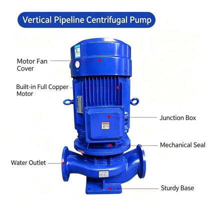
|
|
ISG Vertical Pipeline Centrifugal Pump parallel operation parametersISG Vertical Pipeline Centrifugal Pump Parallel Operation Parameters: Engineering the Combined SystemRunning multiple ISG vertical pipeline centrifugal pumps in parallel is one of the most common strategies for handling variable demand, meeting peak flow requirements, or providing operational redundancy. It sounds straightforward on paper — connect two or more units to the same suction and discharge headers and let them share the load. In reality, parallel operation introduces a host of parameters that must be understood and controlled or the system will either waste energy, starve individual units, or fail catastrophically. The ISG platform has specific characteristics that make parallel configurations behave differently from horizontal end-suction arrangements, and ignoring those differences is a recipe for operational headaches.
Why Parallel Operation Makes Sense for the ISG PlatformThe ISG vertical pipeline pump has a compact, inline footprint. It bolts directly into a pipe run with flanged connections on the same centerline. This physical simplicity makes it one of the easier pump types to parallel — there are no heavy baseplates to align, no flexible couplings spanning long distances, no complicated piping transitions between units. Multiple ISG pumps can share a common suction header and a common discharge header with relatively short connecting runs, which keeps hydraulic losses low and keeps the installation clean. But compact size also means compact motor frames. Each unit has its own integrated motor, typically a few kilowatts to a few dozen kilowatts depending on the model. When you parallel two, three, or four of these units, the combined electrical demand on the supply bus can be substantial. The electrical distribution system must be sized for the worst-case scenario — all units running simultaneously — even if the control strategy is designed to bring them online sequentially. The primary reasons engineers choose parallel ISG configurations are threefold. First, demand varies throughout the day or across seasons, and a single large pump would cycle on and off or throttle heavily, wasting energy and stressing components. Two or three smaller units can be staged to match demand more closely. Second, redundancy matters in applications where continuous flow is non-negotiable — hospital chilled water, fire suppression booster sets, industrial cooling loops. If one unit fails, the remaining units keep the system alive while maintenance happens. Third, lead-lag rotation extends overall service life. Instead of one pump running for 8,000 hours a year while the other sits idle, both can alternate, distributing wear evenly. The Critical Parameters That Govern Parallel BehaviorThe single most important parameter in parallel ISG operation is not flow or head — it is the shape and slope of the combined pump curve relative to the system curve. When two identical ISG pumps run in parallel, the combined flow at any given head is roughly double the flow of a single unit at that same head — but only up to a point. At very low flow rates, near shut-off, the combined curve does not double cleanly. One pump may be operating at or near zero flow while the other carries most of the load. This is because the system curve and the individual pump curve intersect at different points for each unit, and small manufacturing tolerances in impeller diameter, wear, or motor speed cause enough difference that one unit "takes" the flow while the other essentially idles. This phenomenon — called uneven load sharing — is the defining challenge of parallel operation. It is not unique to ISG pumps, but the vertical pipeline form makes it slightly more sensitive because the short, rigid suction and discharge connections offer less hydraulic resistance to balance the flow between units. In a system with long, high-friction headers, the resistance itself helps equalize the flow. With ISG pumps sitting close together on short headers, the hydraulic balancing effect is weaker, and you need to pay more attention to other methods. Head matching is the parameter that controls this. If two parallel ISG pumps have even a 5 percent difference in their shut-off head — due to manufacturing variation, impeller trim, or wear — the unit with the higher head will attempt to deliver more flow. At the combined operating point, this can mean one pump runs at 110 percent of its rated flow while the other runs at 60 percent. The overloaded unit overheats, its seal wears faster, its motor draws excess current. The underloaded unit may operate below its minimum continuous stable flow, causing internal recirculation, vibration, and temperature rise in the volute. For this reason, when specifying parallel ISG units, the heads must be matched as closely as possible — ideally within 2 to 3 percent at the design flow point. This often means ordering pumps from the same production batch, or specifying tighter manufacturing tolerances on impeller diameter and vane geometry. Field balancing through impeller trimming is possible but adds cost and time. Motor speed matching is equally critical. Two ISG pumps running at slightly different speeds — say, one at 2880 rpm and one at 2920 rpm due to motor slip differences — will not share load evenly. The faster unit generates more head and grabs more flow. In a 60Hz system where nominal speeds are 3500 and 3550 rpm, this variation can be more pronounced. Measuring actual shaft speed with a tachometer during commissioning and verifying that all parallel units are within 1 percent of each other is a step that too many installations skip. System Curve Interaction and the Risk of RunoutThe system curve is the other half of the equation, and in parallel ISG operation, its slope determines whether the arrangement is stable or dangerous. A steep system curve — one where small changes in flow produce large changes in head, typical of systems with long pipe runs, many fittings, or high static head — tends to force parallel pumps toward more even load sharing. If one unit tries to grab more flow, the system resistance rises sharply and pulls it back. The operating point self-corrects to some degree. A flat system curve — one where head barely changes with flow, typical of short pipe runs, low static head, or systems with large storage tanks — offers almost no corrective force. In this scenario, the pump with the slightly higher head curve will dominate, and the other unit may contribute almost nothing. Worse, if the dominant pump trips or shuts down, the remaining unit suddenly must handle the full system demand. If that single unit cannot deliver the required flow at the available head, the system fails — not gradually, but abruptly. This is why parallel ISG installations in flat-curve systems need either automatic load-sharing controls, check valves on each discharge to prevent backflow into the idle unit, or careful staging logic that ensures no single pump ever has to handle the entire system alone. NPSH behavior in parallel operation also deserves attention. Each ISG unit draws from the same suction header. If the header is undersized or if multiple units are pulling simultaneously, the velocity in the suction header increases, friction losses rise, and NPSHa at each pump inlet drops. This is a compounding effect — the more units you run, the less suction head each one sees. Calculate NPSHa at full parallel operation, not at single-unit operation. If the margin is tight at one pump, it may become negative at three. Temperature rise in the suction header is another factor that gets overlooked. When multiple ISG pumps recirculate fluid through a closed loop — common in heating system boosting — the combined heat input from all motors adds up. The fluid temperature at the suction of the last pump to start may be noticeably higher than when only one unit was running, which reduces NPSHa further and increases the risk of cavitation in that unit. Control Strategy and What Happens When One Unit FailsThe control system is not a separate topic — it is part of the parallel operation parameter set. How you sequence the pumps on and off, how you detect a failed unit, and how you respond to that failure defines whether the parallel arrangement delivers its intended benefits or creates new problems. Lead-lag control with equal runtime accumulation is the most common strategy. A controller alternates which pump runs first, and a runtime meter on each unit triggers the switch. This works well for redundancy and even wear distribution, but it does nothing to prevent uneven load sharing at the moment both units are online. You still need the pumps to be closely matched in head and speed. Demand-based staging — bringing additional units online as flow demand rises — is more energy-efficient but requires a reliable flow or pressure sensor in the discharge header and a controller with proper sequencing logic. The staging intervals should be sized so that no single pump is forced to operate far outside its efficient range. If the gap between stages is too large, one pump may be heavily overloaded while the next one is still off. If the gap is too small, you get excessive cycling, which shortens motor and starter life. When one unit in a parallel ISG set fails — motor burnout, seal failure, impeller damage — the remaining units must absorb the full system demand instantly. This transient event produces a pressure dip in the discharge header, a potential flow surge through the check valve on the failed unit's discharge, and a sudden load increase on the surviving motors. If the remaining pumps cannot handle the full demand at the available head, the system pressure collapses. In fire suppression or critical cooling applications, this is not acceptable. The practical solution is to verify, during the design phase, that any combination of N-1 units (where N is the total number in parallel) can meet the minimum required system demand. If you have three pumps and any two must be able to sustain the system, the two-pump capacity must exceed the minimum demand by a comfortable margin — not just barely meet it. This often means oversizing the individual units slightly compared to a single-pump design, which is a cost trade-off that must be made explicit in the specification. Vibration monitoring across the parallel set provides early warning of load imbalance. If one ISG unit begins running louder or hotter than its partner while both are supposedly online, something is wrong — a clogged impeller, a failing bearing, a partially closed valve on its discharge. Do not wait for failure. Install vibration sensors or at minimum temperature probes on each unit's bearing housing and set alarms at 10 to 15 percent above baseline. Catching a developing problem in one unit of a parallel set protects not just that unit but the entire system's reliability. |