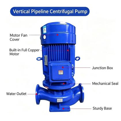
Seal leakage on an ISG vertical pipeline centrifugal pump is one of the most commonly misunderstood operating conditions, as many maintenance teams treat every visible drip as an immediate failure, while others ignore slow weeping that signals developing internal damage. Understanding practical, field-verified allowable leakage standards helps teams distinguish between normal, acceptable run-in behavior and conditions that require immediate intervention to prevent unplanned downtime.

Start every leakage assessment by first classifying the exact fluid and service conditions the pump operates under, since these factors directly define what counts as acceptable leakage. For non-hazardous, non-toxic plain water service at ambient temperature, a very small, steady amount of leakage acts as natural lubrication and cooling for the precision seal faces, preventing dry contact that would cause rapid overheating and face scoring. For hot water, hydrocarbon, or chemically aggressive process fluids, even a tiny visible drip can present safety risks or environmental hazards, so allowable limits drop to near-zero for these applications. For sanitary or food-grade service, no leakage of any kind is permitted, as even the smallest amount of weeping can create contamination risks that violate strict process compliance requirements.
Next, evaluate the leakage pattern and rate against widely accepted field service benchmarks to separate normal behavior from developing faults. For standard single mechanical seals in general water service, a slow leakage rate of up to 10 drops per minute is widely considered acceptable during normal steady-state operation, and this rate often drops further after the seal completes its initial short break-in period. Any leakage that forms a continuous stream, sprays outward from the seal gland, or accumulates into small puddles on the baseplate far exceeds the allowable threshold, and signals serious face damage, incorrect seal installation, or excessive axial shaft movement. Weeping that appears only at the O-ring or gasket joint between the seal gland and casing, rather than at the rotating seal face, points to secondary seal damage rather than primary face wear, and this condition should not be dismissed as normal even if the drip rate appears very slow.
Once you have confirmed the leakage rate and pattern fall outside acceptable limits, trace the root cause before replacing any seal components, to avoid repeating the same failure shortly after reassembly. Check the shaft axial play first with the pump de-energized, as excessive thrust bearing wear that allows the rotor to shift back and forth will constantly change seal face compression and create unstable leakage that no new seal can resist. Verify the seal flush line is not blocked, restricted, or isolated by a closed valve, since loss of flush flow starves the seal faces of cooling and lubrication, leading to rapid face deformation and a sudden spike in leakage that can easily exceed allowable standards. Confirm the pump has not been operating far outside its design flow range for extended periods, as severe internal recirculation creates localized pressure spikes that can momentarily separate the seal faces and introduce unexpected leakage that was not present during normal operation.
Document every leakage observation, measured drip rate, and corrective action in the pump’s permanent service log, so you can track trends over time and spot slow, gradual leakage growth before it crosses the acceptable threshold. This practical, application-specific approach to leakage assessment aligns with decades of industrial field maintenance experience, reduces unnecessary seal replacement work, and helps extend the reliable operating life of every installed seal across the pump’s service cycle.