Internal flow channel design forms the hydraulic foundation of ISG vertical pipeline centrifugal pump performance, directly influencing energy transfer efficiency, running stability, and long-term wear resistance across different working conditions. This design work focuses on guiding fluid smoothly from the pump inlet through the impeller and volute to the discharge port, avoiding unnecessary flow losses, turbulence, and local pressure fluctuations that would degrade overall system performance.
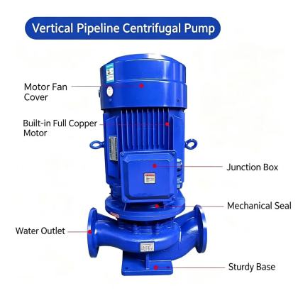
Inlet flow path optimization for uniform fluid entry
The section connecting the pipeline inlet to the impeller eye is carefully shaped to eliminate sudden changes in flow velocity and uneven velocity distribution before fluid enters the rotating impeller. A gradual, streamlined transition profile prevents the formation of low-pressure dead zones that could trigger early cavitation near the suction side, while ensuring fluid reaches every part of the impeller blade leading edge at nearly consistent speed. This design reduces pre-rotation of incoming fluid that would otherwise create unnecessary hydraulic losses before the impeller can effectively transfer energy to the medium. Even when the pump operates at flow rates slightly below the nominal design point, the optimized inlet flow path maintains stable flow direction and minimizes local flow separation that could cause vibration or noise.
Impeller internal passage geometry and hydraulic profiling
Each flow channel between two adjacent impeller blades is precisely contoured using computational fluid dynamics analysis to balance flow acceleration, pressure rise, and friction loss across the full span of the blade. The channel width changes gradually from the impeller eye to the blade outlet, avoiding abrupt dimensional shifts that would create localized turbulence and dissipate useful energy as heat. Both the hub and shroud surfaces of the impeller are finished to a smooth continuous profile that guides fluid along the intended trajectory without unwanted flow detachment or recirculation zones. This carefully calibrated geometry ensures that the majority of kinetic energy generated by the rotating impeller is converted into usable pressure head rather than being wasted in chaotic internal flow patterns.
Volute and discharge flow channel pressure recovery structure
The volute surrounding the impeller is designed with a progressively increasing cross-sectional area that matches the flow discharged from the impeller at different angular positions, collecting fluid evenly and guiding it toward the discharge nozzle. This gradual expansion converts high-velocity flow exiting the impeller into stable pressure with minimal shock loss, while preventing uneven pressure distribution around the impeller periphery that would generate unbalanced radial forces on the pump shaft. The transition section from the volute throat to the discharge flange maintains a gentle diffusion angle that avoids flow separation on the inner wall, further improving overall pressure recovery efficiency. Even during extended operation near the maximum allowable flow point, this volute structure keeps internal flow patterns stable and prevents excessive radial load that would accelerate bearing wear.
Wear-resistant and flow-stabilizing treatment on flow channel surfaces
All wetted surfaces inside the pump casing, impeller, and transition sections are treated to reduce surface roughness, lowering frictional resistance between the fluid and metal walls that would otherwise reduce hydraulic efficiency over time. The geometric alignment between adjacent flow channel components is strictly controlled to eliminate step misalignments that could disrupt smooth flow and create local eddy currents at component joints. This attention to surface quality and geometric consistency helps maintain consistent hydraulic performance throughout the pump’s service life, even when handling media containing small amounts of fine solid particles that would otherwise cause accelerated erosion in high-velocity zones.


