|
|
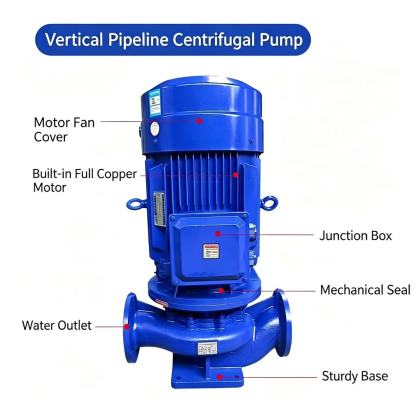
ISG Vertical Pipeline Centrifugal Pump high efficiency hydraulic modelThe high efficiency hydraulic model of the ISG vertical pipeline centrifugal pump is developed to maximize energy transfer between the rotating impeller and the process fluid, while minimizing the hydraulic losses that often reduce overall system performance in general-purpose pipeline pump designs. This model is built on decades of accumulated field test data covering thousands of operating points across different flow rates, fluid viscosities, and system pressure conditions, so its performance characteristics are validated against real-world operating scenarios rather than only ideal laboratory conditions. Every geometric parameter of the flow components is refined through repeated physical testing, ensuring the final design delivers stable high efficiency across a far wider operating window than standard hydraulic configurations.
Impeller Blade Profile and Flow Guidance GeometryThe impeller blades use a carefully contoured three-dimensional profile that guides fluid smoothly from the suction eye all the way to the blade outlet, eliminating sudden changes in flow velocity that would otherwise generate unnecessary turbulence and energy waste. The inlet edge of each blade is shaped to match the incoming flow angle under nominal operating conditions, reducing impact losses that occur when fluid strikes the blade surface at an incorrect angle, especially when the pump is running at flow rates slightly below or above its best efficiency point. The number of blades and their wrap angle are calibrated to balance flow uniformity and frictional surface area, preventing flow separation that can create low-efficiency recirculation zones near the impeller outlet. This precise profiling also reduces unsteady hydraulic forces acting on the shaft, which in turn lowers vibration levels and allows the pump to maintain peak efficiency even after thousands of hours of continuous operation. The outlet blade angle is optimized to convert as much kinetic energy as possible into stable pressure rise inside the pump casing, rather than dissipating that energy as chaotic flow that generates heat and noise. Volute Casing Flow Conversion DesignThe volute surrounding the impeller is engineered with a progressively expanding flow area that matches the discharge flow from each impeller blade passage, collecting the high-velocity fluid and gradually decelerating it to convert kinetic energy into usable static pressure. The cross-sectional shape of the volute is not a simple uniform circle, but a custom contoured profile that keeps flow velocity consistent around the full 360-degree path, avoiding localized high-velocity zones that would create excessive friction losses. At the volute discharge throat, a carefully designed diffuser section further reduces flow velocity before the fluid enters the discharge pipeline, ensuring that very little residual kinetic energy is wasted at the pump outlet. This careful flow conversion work means that a larger percentage of the motor’s input power goes directly into increasing fluid pressure, rather than being lost as heat or turbulence inside the pump casing. Even when the pump operates at partial load, the volute geometry maintains stable flow patterns that prevent the sharp efficiency drop that many basic pump designs experience when moving away from their design flow. Suction Flow Stability and NPSH OptimizationThe high efficiency hydraulic model includes a specially shaped suction inlet that guides fluid evenly into the impeller eye, maintaining uniform flow velocity across |