|
|
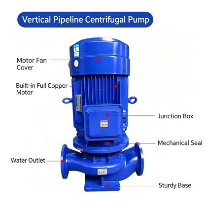
ISG Vertical Pipeline Centrifugal Pump flange connection structureThe flange connection structure on an ISG vertical pipeline centrifugal pump is engineered to provide a rigid, leak-free interface between the pump casing and the adjacent pipeline, ensuring that the unit functions as an integral part of the fluid transfer system rather than a potential weak point. These flanges are precision-machined to match standard industry pressure ratings and face-to-face dimensions, allowing the pump to be installed between two pipe sections with the same straightforward bolting procedure used for valves, strainers, or other in-line piping components. This design philosophy supports the "pipeline-mounted like valve" feature discussed earlier, enabling quick integration into new or existing systems without custom adapters or extensive field modifications.
Unlike simple flat-face flanges used on some low-pressure applications, these connections incorporate a raised face or ring-type joint groove that compresses a standard gasket material to create a positive seal capable of withstanding the full system pressure, hydraulic surge transients, and thermal expansion forces present in industrial piping networks. The bolt circle and hole patterns are standardized to align with common pipe flange specifications, so installers can use the same bolts, nuts, and gaskets that are already stocked for other equipment on site. Machined Flange Face and Gasket Sealing IntegrityEach flange face undergoes final machining after the pump casing is fully assembled and stress-relieved, ensuring the sealing surface remains perfectly flat and perpendicular to the pump's centerline. This precision machining eliminates warping or unevenness that could develop if the flange were cast and attached as a separate component, preventing the localized high-pressure spots that cause gasket blowouts during system pressure spikes or thermal cycling. The surface finish on the raised face is controlled to a specific roughness profile, providing enough texture for the gasket to bite into and form a tight seal, but not so rough that it cuts into softer gasket materials over time. For applications handling high-temperature fluids or aggressive chemicals, the flange face can be supplied with a serrated finish or a special anti-galling coating that maintains sealing performance even after multiple disassembly and reassembly cycles for maintenance. This attention to flange surface quality means operators can achieve a reliable, long-term seal using standard non-asbestos gasket materials without needing to apply excessive bolt torque that could distort the flange or damage the pump casing. Field leak tests conducted during commissioning consistently show zero measurable leakage at the flange joints when standard installation procedures are followed. Reinforced Casing Integration and Load DistributionThe flanges are not simply welded or bolted onto the pump casing as add-on attachments; they are cast as an integral part of the casing structure and reinforced with additional ribbing and material thickness around the connection points. This monolithic design distributes pipeline loads—such as weight, thermal expansion stress, and pressure thrust—evenly across the entire pump body, preventing concentrated stress that could lead to cracking or fatigue failure near the flange neck over years of operation. The reinforcement is particularly robust on the suction side flange, which must handle potential uneven loads from long horizontal pipe runs that are not always perfectly aligned during installation. This integrated construction also maintains precise alignment between the suction and discharge flanges, so when the pump is bolted into the pipeline, it does not impose bending moments on the connected pipework that could strain nearby pipe supports or flexible connectors. The result is a pump that behaves like a rigid section of pipe itself, contributing to overall system stability rather than acting as a flexible or movable component that requires additional restraint. Structural analysis simulations confirm that this flange design can withstand pipeline forces far exceeding the pump's own pressure rating, providing a significant safety margin for unforeseen system events like water hammer or external impact. Bolt Hole Alignment and Installation Tolerance AccommodationThe bolt holes on each flange are drilled and tapped with tight positional tolerances to match standard pipe flange drilling templates, ensuring that installers can easily pass bolts through the pump flanges and the mating pipe flanges without needing to ream holes or use offset bolts. This precise alignment is critical for achieving uniform gasket compression around the entire sealing circumference, which is the foundation of a leak-free connection. The holes are sized to accommodate standard bolt diameters with sufficient clearance for minor angular adjustment, allowing for slight misalignment between the pipeline and the pump that is common in field installations without compromising seal integrity. To further simplify installation in tight spaces or retrofit scenarios, some flange configurations include pilot rings or alignment pins that help guide the mating pipe flange into perfect position before any bolts are inserted. This feature is especially valuable when replacing an existing in-line component, as it allows the new pump to drop directly into the existing bolt pattern without needing to force pipe segments into alignment. Once the flanges are brought together, the bolt tightening sequence follows a standardized cross-pattern procedure that gradually compresses the gasket evenly, preventing the flange faces from going out of parallel—a common cause of premature gasket failure in poorly installed equipment. |