|
|
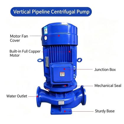
ISG Vertical Pipeline Centrifugal Pump inline installation procedureProper inline installation of an ISG vertical pipeline centrifugal pump directly affects long-term operational stability, noise levels, and overall system service life. When the pump is mounted directly in line with existing piping, every step from site preparation to final commissioning must follow consistent, field-proven practices to avoid common issues such as shaft misalignment, piping-induced stress, and unexpected downtime.
Site and Piping Layout PreparationBefore any physical installation begins, confirm the selected location provides enough clearance for routine inspection, seal replacement, and future disassembly without removing adjacent piping sections. The mounting surface must be flat, rigid, and capable of absorbing dynamic loads generated during full-speed operation. Avoid placing the unit in areas with restricted airflow around the motor, as sustained high ambient temperatures can shorten winding insulation life. All connected piping should have independent support structures positioned close to the pump flanges, so the full weight of suction and discharge lines never rests directly on the pump casing. This prevents casing distortion, shaft misalignment, and premature mechanical seal failure that often occur when piping loads are transferred to the pump body. The centerline of both suction and discharge pipes must align perfectly with the pump’s inlet and outlet flanges before any bolts are tightened. Flange Connection and Alignment CheckPlace a full-face gasket between the pump flange and the corresponding piping flange, then insert all flange bolts by hand before applying any torque. Tighten bolts gradually in a crisscross pattern to distribute clamping force evenly across the entire sealing surface. Uneven tightening can warp the flange face, create leak paths, and introduce hidden stress that distorts the pump casing over time. After all flange connections are secure, rotate the pump shaft by hand through the full range of motion. The shaft should turn smoothly, with no noticeable scraping, binding, or irregular resistance. Even minor contact between rotating and stationary components during this manual check will amplify once the motor reaches operating speed, leading to elevated vibration levels and accelerated wear of internal components. Pre-Startup Priming and Commissioning StepsFully open the suction side valve to allow process fluid to enter the pump casing, then open the dedicated air vent plug on the pump body. Keep the vent open until a steady stream of liquid flows out without trapped air bubbles, then close the vent securely. Trapped air inside the pump cavity can cause vapor locking, which prevents the pump from building proper pressure even when the motor runs at full design speed. Before the pump reaches full continuous operation, perform a brief motor rotation test with the discharge valve nearly closed. Confirm the shaft rotates in the correct direction as specified in the equipment documentation, since reverse rotation can damage impeller fasteners and internal hydraulic components |