|
|
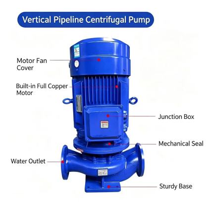
ISG Vertical Pipeline Centrifugal Pump vertical alignment requirementAccurate vertical alignment for ISG vertical pipeline centrifugal pumps is a critical field practice that directly reduces operational vibration, extends bearing service life, and prevents unnecessary stress transfer between the pump body and connected piping. Even minor deviations from specified alignment tolerances can lead to accelerated seal wear, inconsistent hydraulic performance, and unplanned maintenance events that disrupt continuous system operation.
Reference Surface and Pre-Measurement PreparationBefore taking any alignment readings, confirm the base mounting surface is fully cleaned of rust, leftover welding slag, and residual construction debris. All mounting fastener locations must be free of burrs that could create uneven support points under the pump frame. Place precision leveling shims directly under each mounting foot, ensuring shim stacks are no thicker than necessary and no individual shim extends beyond the edge of the foot contact area. Verify that all connected piping is fully supported and no external forces are pulling or pushing on the pump flanges during the alignment process. Any piping stress applied to the casing will shift the pump’s reference position, leading to alignment readings that appear correct during installation but drift immediately once the full piping system is pressurized. The pump shaft should rotate freely by hand through its full travel range before any measurement tools are mounted, to eliminate binding that could skew indicator readings. Shaft and Coupling Alignment TolerancesMount a dial indicator securely on one half of the coupling, with the indicator plunger resting firmly against the outer diameter and face of the opposite coupling half. Rotate both shafts together slowly through a full 360-degree cycle, recording total indicator runout values at the top, bottom, left, and right positions. The maximum allowable parallel offset should not exceed 0.05 millimeters for most standard operating speeds, while face angular deviation must stay below 0.03 millimeters across the full coupling diameter. If readings fall outside acceptable limits, adjust the thickness of leveling shims under specific mounting feet to raise or lower the corresponding side of the pump or motor frame. Make small, incremental adjustments rather than large single shim changes, and recheck all indicator values after each adjustment to track how the alignment profile shifts across the full coupling rotation. Never force the coupling into alignment by tightening or loosening flange bolts, as this will introduce hidden casing stress that distorts internal component positioning. Thermal Expansion and Operational VerificationAfter initial cold alignment is completed, account for expected thermal growth during normal operating conditions. When process fluid at elevated temperatures flows through the pump casing, the metal structure will expand upward and shift the shaft centerline slightly. This predictable movement should be factored into cold alignment settings, so the shaft remains perfectly concentric once the unit reaches steady-state operating temperature. Once the pump has run under full load for several hours and reached thermal equilibrium, shut down the system safely and perform a final post-warm alignment check. Compare these readings against the initial cold alignment data to confirm no unexpected movement or structural settling has occurred. Document all final measured values for future reference, so subsequent maintenance teams can quickly identify any alignment drift that develops over thousands of operating hours. |