|
|
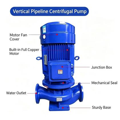
ISG Vertical Pipeline Centrifugal Pump piping support requirementProper piping support design for ISG vertical pipeline centrifugal pumps eliminates external stress transfer to the pump casing, preserves precise internal component alignment, and prevents long-term structural deformation that would otherwise shorten equipment service life. When suction and discharge lines are not adequately restrained, even normal system pressure fluctuations can introduce cyclic loads that lead to flange leakage, shaft misalignment, and unexpected mechanical failure. Load Distribution and Support PositioningAll piping connected directly to the pump must carry its own weight, fluid mass, and dynamic reaction forces through independent support structures, rather than transferring these loads to the pump body. The first support on the suction side should be installed within 300 to 500 millimeters of the pump inlet flange, and the first support on the discharge side should be placed at a similar distance from the pump outlet flange. This arrangement prevents excessive cantilever deflection that would pull or push the pump casing out of its calibrated alignment position. Avoid placing heavy piping components such as valves, expansion joints, or filter units directly adjacent to the pump flanges without dedicated local supports. These components add concentrated mass that creates significant bending moments when the system operates under pressure and temperature cycles. Each support location must be anchored to a rigid structural base that can absorb both static weight and transient hydraulic shock loads generated during pump startup or sudden valve closure.
Support Type Selection for Different Operating ConditionsFor horizontal piping runs connected to the pump, use rigid pipe hangers or load-bearing base supports that restrict vertical movement while allowing controlled axial displacement to accommodate thermal expansion. These supports prevent vertical sag that would create misalignment between the piping centerline and the pump flange face. For lines carrying high-temperature process fluid, add spring-loaded supports at strategic intervals to maintain consistent load distribution even as piping expands upward during heat-up cycles. Install dedicated guide supports near the pump flanges to limit lateral movement of the piping, which prevents side loads from being applied to the pump casing during system pressure transients. These guides allow free axial movement for thermal growth while restraining horizontal displacement that could shift the pump’s carefully calibrated shaft alignment. For large-diameter piping systems, add intermediate supports along long straight runs to keep overall piping deflection well below 1 millimeter per meter of pipe length. Expansion Compensation and Stress ControlNever use the pump itself as an anchor point to absorb thermal expansion movement in connected piping. All axial displacement generated by temperature changes must be managed through properly positioned expansion loops, bellows elements, or dedicated expansion joints installed at a safe distance from the pump casing. This prevents large axial forces from pushing or pulling on the pump flanges, which would distort the casing and create internal contact between rotating and stationary components. After all piping and supports are fully installed, perform a final visual check by loosening the pump flange bolts one at a time. There should be no visible gap or misalignment between the piping flange and the pump flange face when bolts are removed. If any offset or angular misalignment appears, adjust the adjacent piping supports to bring the flanges back into perfect concentric alignment before re-tightening the connection. This simple field verification step eliminates nearly all piping-induced stress issues that would otherwise appear after the system goes into continuous operation. |