|
|
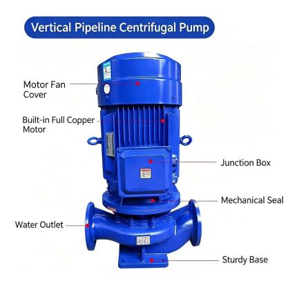
ISG Vertical Pipeline Centrifugal Pump series installation instructionA properly executed series installation for ISG vertical pipeline centrifugal pumps ensures stable parallel or staged operation, avoids mutual flow interference, and maintains consistent system performance across different load conditions. This kind of setup is commonly used in applications that require extended head coverage, where a single unit cannot deliver the required pressure rise across the full operating range. Every stage of installation must account for shared piping characteristics, individual unit alignment, and hydraulic balance between connected pumps, rather than treating each pump as a separate standalone installation. Field technicians often overlook the unique interaction between series units, which can lead to uneven load distribution, accelerated seal wear, and unexpected cavitation events during variable flow operation.
Pre-installation hydraulic and site layout confirmationBefore any physical installation begins, map out the full system hydraulic profile to confirm that each pump in the series will operate within its acceptable performance window at all expected flow rates. The first pump in the sequence must deliver enough inlet pressure to the second unit to keep net positive suction head available well above the required minimum value. This prevents the second pump from pulling a partial vacuum at its suction side, even during temporary flow fluctuations. The installation site must provide unobstructed access around every individual pump for routine inspection, bearing temperature checks, and future maintenance. All units should be positioned along a straight, aligned pipe run to avoid unnecessary elbow fittings that introduce additional flow resistance. The foundation for each pump must be sized to handle not just its own static weight, but also the combined dynamic forces generated when two or more units operate in sequence. At this stage, technicians should also verify that all independent pipe support points are marked clearly on the layout drawing. No part of the series piping should transfer structural load directly to any pump casing, as this will introduce flange misalignment and hidden stress that disturbs rotor alignment over time. Inter-stage piping and accessory matchingThe pipe section connecting the discharge of the first pump to the suction of the second pump must maintain the same or larger internal diameter as the respective pump flanges. Reducing pipe size between units creates unwanted flow acceleration, pressure drop, and turbulence that disrupt smooth flow entry into the second pump impeller. All flange faces on inter-stage piping must be parallel and perfectly aligned before any bolts are installed, with no forced adjustment to pull the piping into position. Between each pump in the series, install a pressure gauge tap point on both the suction and discharge side of every unit. These points allow operators to monitor the actual pressure rise across each individual pump, rather than only reading the total system pressure at the far upstream and downstream locations. This makes it easy to identify if one unit is underperforming, running at off-design conditions, or carrying an unfair share of the total system head. A full port isolation valve should be fitted on the suction and discharge side of every pump in the series arrangement. This allows a single unit to be isolated for inspection or minor repair without draining the entire system, as long as the remaining operating units are not pushed beyond their safe performance limits. A properly sized check valve on the discharge of each pump prevents reverse flow through an idle unit when other pumps in the sequence are still running. Alignment verification and staged commissioningAfter all pumps and inter-stage piping are bolted into place, perform a full vertical and horizontal alignment check on every individual pump unit. Even small misalignment errors that would be acceptable on a single standalone installation become amplified in a series setup, because residual vibration from one unit propagates through the shared piping and affects the next unit in line. Use a precision level on machined reference surfaces of each pump baseplate, and confirm that shaft concentricity between pump and motor falls within accepted field tolerances. Before starting any unit, fill the entire suction line and every pump casing with liquid, and open all vent plugs on each pump body until a steady stream of liquid flows out with no trapped air remaining. Trapped air in one pump will cause uneven flow through the entire series, leading to pressure spikes, unstable operation, and possible dry running damage to mechanical seals. Commission the system one pump at a time, rather than energizing all units simultaneously. Start the first pump in the sequence with its discharge valve partially closed, confirm stable pressure and current readings, then bring the second pump online gradually. Monitor vibration levels, bearing temperatures, and pressure readings across every unit for an extended period during the first full load run. This staged approach reveals any hidden hydraulic imbalance before the system is handed over for continuous normal operation. |