|
|
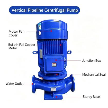
ISG Vertical Pipeline Centrifugal Pump pipeline stress elimination methodProper pipeline stress elimination is one of the most overlooked yet critical steps for long-term reliable operation of an ISG vertical pipeline centrifugal pump. Even minor misalignment or uneven force transfer across flanges can introduce hidden loads that gradually wear down bearings, damage mechanical seals, and cause unexpected performance drift over months of continuous service. Many installation teams focus on quick bolting and commissioning, but they skip the systematic stress removal procedures that directly extend pump service life and reduce unplanned downtime.
Understanding How Pipeline Stress Damages Pump ComponentsWhen two mating flange faces are misaligned, even by a small margin, the resulting pipeline stress does not simply disappear after the bolts are tightened. Instead, it transfers directly into the pump casing, shaft, and bearing assembly, creating persistent abnormal internal loads that were never accounted for in the original equipment design. These uneven forces pull the pump shaft slightly off its ideal vertical axis, breaking the precise alignment established during factory rotor balancing. Over time, this misalignment triggers a predictable set of failure modes that most maintenance teams misattribute to normal wear. Seal faces begin to experience uneven contact pressure, leading to localized friction and premature leakage that often appears within the first few hundred operating hours. Static vibration from residual stress creates micro-movement between bearing rollers and races, gradually wearing away the precision surface finish that keeps rotation smooth. Under static standby conditions, constant overload force can indent bearing race surfaces, creating permanent deformation that generates noticeable noise once the pump restarts. Even lubrication performance suffers, as abnormal load breaks down the oil film and allows metal-to-metal contact that leads to corrosion and spalling on critical rolling surfaces. In severe cases, accumulated stress can subtly warp the pump casing and shift impeller position, changing the designed flow path and reducing actual discharge capacity far below the rated performance curve. Pre-Welding Alignment and Stress Control ProceduresThe most effective pipeline stress elimination starts long before the final weld is completed. Rushing this stage often locks permanent stress into the system that no later adjustment can fully remove. The first basic rule is that the mating pipeline flange must naturally align with the pump flange without any external pulling force. The gap between the two faces should never exceed twice the thickness of the installed gasket, and all bolt holes must line up so that each bolt can slide into place freely without the help of pry bars, cable pullers, or long leverage tools. Any attempt to force alignment with external tools will immediately introduce hidden stress that transfers directly into the pump body. Before starting any welding work, place a temporary blind flange and standard gasket between the pump flange and the incoming pipeline flange. This protective setup ensures that welding spatter, heat distortion, and electrical current will not damage the pump internal components during the process. Most importantly, connect the welding grounding clamp directly to the pipeline side flange, never to the pump casing itself. Stray welding current passing through the pump bearings can create tiny electric arcs that leave micro-pits on rolling surfaces, a hidden damage that usually only reveals itself months later through premature bearing failure. Begin with small tack welds at evenly spaced points around the flange circumference, working in opposite directions to distribute heat evenly and avoid uneven distortion. Allow the tack welds to cool completely for at least 10 minutes before proceeding to the next step. Then perform stitch welding across opposite sides of the flange, following the same balanced heat distribution method used for cast iron welding to minimize thermal warpage. After completing the initial reverse stitch weld passes, continue with full welding using standard recommended electrode specifications, maintaining consistent travel speed and heat input throughout the entire joint. Post-Welding Verification and Final Stress ReleaseOnce the welding joint has fully cooled down to ambient temperature, disconnect all bolts, remove the temporary blind flange, and install the final service gasket. This step is where you confirm that no residual stress was locked into the connection during the welding process. Check every bolt hole again to make sure each bolt can slide smoothly into position without any prying or forcing action. Re-measure the gap between the two flange faces all around the circumference to confirm it still stays within the allowable tolerance, no more than twice the gasket thickness at any point. If any bolt requires extra force to enter the hole, or if the gap varies significantly around the flange, the pipeline still carries residual stress that needs correction. To release remaining stress, loosen all adjacent pipeline support clamps and allow the pipe to settle into its natural free position. Tap the pipeline gently along its length with a soft mallet to encourage minor movement and release hidden tension built up during cooling. Readjust the pipe supports carefully so that they hold the pipeline in its natural aligned position, rather than pulling or pushing it to match a misaligned pump flange. This ensures that the full weight of the pipeline never rests on the pump casing, and no external force tries to pull the pump out of its precise vertical alignment. After all supports are properly secured, tighten the flange bolts in a diagonal sequence, gradually increasing torque in multiple small steps to distribute clamping force evenly across the entire joint. When this procedure is completed correctly, the pump shaft remains perfectly aligned with the motor shaft, the bearing assembly operates under only the designed dynamic loads, and the mechanical seal faces maintain consistent parallel contact through every operating cycle. The entire system avoids the slow, hidden damage that unaddressed pipeline stress introduces, allowing the pump to deliver stable performance through years of continuous operation without unexpected breakdowns. |