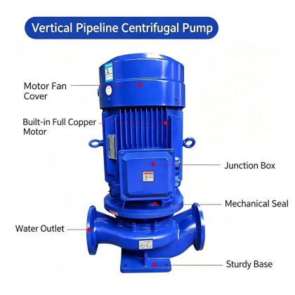
Proper suction side installation directly affects the stable operation, service life, and overall efficiency of ISG vertical pipeline centrifugal pumps. Even minor misalignment or unregulated layout on the suction line can lead to cavitation, uneven flow distribution, and unexpected mechanical seal failures that force unplanned shutdowns. Every step of the suction side setup should follow field-verified engineering practices to ensure consistent fluid delivery and long-term system reliability.
Suction Line Straight Run Requirements Before Pump Inlet
A sufficient straight pipe section before the pump inlet is critical for eliminating turbulent flow and uneven velocity profiles that form after elbows, tees, or partially closed valves. Most field engineering guidelines recommend maintaining a straight run equivalent to no less than five times the nominal pipe diameter between the last fitting and the pump suction flange. This length allows fluid to stabilize into a uniform, parallel flow pattern before it enters the pump impeller, reducing the risk of localized low-pressure zones that trigger cavitation. When space constraints in compact pump rooms make the full recommended straight run unachievable, flow straighteners installed between the last elbow and the pump inlet can help mitigate flow distortion, though their performance should be validated during initial commissioning. Avoid installing any reducers, filters, or branch connections within this reserved straight run area, as these components will create additional flow disturbances that cannot be fully corrected even with extended downstream piping.
Eccentric Reducer Installation and Orientation Rules
Eccentric reducers are necessary when the suction pipe diameter is larger than the pump inlet flange size, and their correct orientation directly prevents air pockets from forming inside the line. For horizontal suction runs that connect to the pump from the side, the flat side of the eccentric reducer must be positioned on the top of the pipe to eliminate any upward-facing gaps where air can accumulate. Trapped air in this area will gradually travel into the impeller, causing intermittent pressure fluctuations, noise, and accelerated wear on impeller vanes over time. If the suction line runs vertically downward toward the pump inlet, concentric reducers can be used safely, as gravity will pull any trapped air back toward the upstream system rather than trapping it in the reducer cavity. Never install an eccentric reducer with its flat side facing downward on a horizontal suction line, as this configuration creates a low spot that collects air and disrupts consistent fluid flow to the pump. All reducer connections must be fully aligned with the adjacent pipe flanges to avoid introducing unnecessary mechanical stress that can distort the pump casing over extended operation.
Suction Side Strainer and Isolation Valve Placement
Strainers and isolation valves on the suction side serve distinct protective purposes, but their placement must follow specific rules to avoid creating unnecessary flow resistance that reduces available net positive suction head. The isolation gate valve should be installed upstream of the strainer, with enough clearance left between the valve body and the strainer basket to allow easy basket removal for periodic cleaning without disconnecting adjacent piping. This layout lets operators fully close the suction valve during routine maintenance without draining the entire upstream system, reducing downtime during filter cleaning or minor pump inspections. The strainer itself must be positioned with its basket access cover facing upward, so that accumulated debris can be easily lifted out during scheduled service without spilling trapped contaminants back into the suction line. The mesh opening size of the strainer should be selected to match the maximum allowable particle size that can pass through the pump impeller without causing clogging or abrasion, and the total open area of the strainer screen should be at least three times the cross-sectional area of the suction pipe to minimize pressure drop across the element. After initial system flushing is complete, the strainer basket should be inspected and cleaned before the first pump startup to remove any construction debris, welding slag, or leftover sealing material that could damage internal pump components.
All suction side piping must be independently supported near the pump inlet flange, so that no weight from the pipe, valves, or connected components is transferred directly to the pump casing. This prevents flange misalignment that can cause external stress on the pump shaft, leading to premature bearing wear and seal leakage. Every connection on the suction line should be leak-checked under full operating pressure before the pump is energized, as even tiny air leaks on the suction side will draw in atmospheric air and create cavitation conditions that damage the pump over thousands of operating hours.


