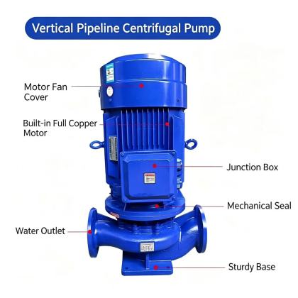
Discharge side installation is one of the most critical stages that determines long-term operational stability, safety, and consistent performance of ISG vertical pipeline centrifugal pumps. Improper layout, misaligned fittings, or poorly selected component positions on the discharge line can introduce water hammer, unnecessary mechanical stress, and flow instability that gradually degrade pump internals even when the suction side setup follows all standard specifications. Every installation step on this side should prioritize controlled flow behavior, structural stress relief, and easy access for ongoing monitoring and maintenance.
Pressure Gauge and Flexible Joint Positioning Near Discharge Flange
Installing a pressure gauge immediately downstream of the pump discharge flange gives operators real-time visibility into actual operating conditions, making it easy to spot abnormal pressure drops or spikes that indicate internal wear, filter clogging, or unexpected system resistance changes. The gauge connection should use a short, isolated tapping point rather than being mounted on a long horizontal pipe run where flow turbulence can cause erratic readings and misleading data. Right after the gauge, a flexible joint should be installed to isolate pump-generated vibration from spreading into the rest of the discharge piping, while also absorbing thermal expansion displacement that occurs as fluid temperature changes during system startup and shutdown. This flexible element must never be stretched or compressed to force flange alignment during installation, because preloading the joint in this way eliminates its ability to absorb movement and can transfer extra axial stress directly to the pump shaft. Leave enough straight pipe length between the pump discharge flange and the first rigid pipe support to avoid overconstraining the connection, so that small movements from thermal expansion or normal operational vibration do not create persistent stress points on the pump casing.
Check Valve and Isolation Valve Layout for Water Hammer Protection
A properly sized check valve installed close to the discharge side of the pump prevents reverse flow from the system when the pump stops unexpectedly, which is essential for stopping rapid backspin that can damage the impeller and motor bearings. Swing-type check valves are commonly used in this arrangement, but they must be oriented correctly to ensure the disc can move freely without binding under normal flow conditions. Directly downstream of the check valve, a full-port isolation gate valve should be fitted to allow operators to fully isolate the pump from the discharge system during inspection, maintenance, or long-term shutdown. This layout lets technicians perform seal replacements or internal inspections without draining the entire downstream piping network, greatly reducing service time and fluid waste. Avoid placing the check valve far away from the pump near the far end of the discharge line, because this leaves a long column of fluid free to rush backward through the pump the moment power is lost, creating severe water hammer that can crack pump components or loosen pipe connections. For high-head installations, adding a small pulsation dampener near the check valve will further absorb sudden pressure transients that form during emergency shutdowns or rapid valve closures.
Discharge Pipe Support and Expansion Compensation Best Practices
Every segment of discharge piping must rest on dedicated, rigid pipe supports that carry the full weight of the fluid-filled line, so no part of the pipe load is ever transferred to the pump discharge flange. Unsupported piping can gradually sag over months of operation, pulling the pump casing out of perfect vertical alignment and creating uneven radial forces on the pump shaft that accelerate bearing wear and mechanical seal leakage. For long discharge lines that run through areas with significant fluid temperature variation, add properly positioned expansion loops or bellows to accommodate thermal growth instead of relying on the pump connection to absorb displacement. All pipe supports should be designed to allow small axial movement of the pipe as it expands and contracts, rather than locking the line completely in place and forcing thermal stress back toward the pump. Where the discharge line connects to overhead piping or elevated system components, install additional guide supports a short distance downstream of the flexible joint to keep the pipe aligned and prevent side loads from twisting the pump discharge flange out of position.
All discharge side flanges should be tightened in a diagonal sequence with evenly applied torque, so no single bolt is over-tightened to create uneven gasket compression that leads to hidden leakage under high operating pressure. After the full discharge line is assembled, perform a hydrostatic test at 1.5 times the maximum working pressure to confirm there are no weak points or joint failures that could release fluid unexpectedly once the pump is brought online.


