Thermal expansion in piping systems creates subtle, persistent mechanical loads that can silently damage ISG vertical pipeline centrifugal pumps over thousands of operating hours, even when every initial alignment and installation step follows standard specifications. As fluid temperature rises or falls during system startup, shutdown, or normal operation, connected metal pipes expand or contract, and these small dimensional changes can translate into unexpected axial, radial, or torsional stress on the pump casing, shaft, and flange connections. A properly designed thermal expansion compensation setup absorbs these movements before they reach the pump, preserving original alignment, extending component service life, and eliminating hidden leak and vibration risks.
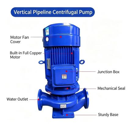
Independent Pipe Support Layout to Isolate Thermal Displacement
The first line of defense against thermal stress on the pump is a network of properly positioned, dedicated pipe supports that guide and absorb piping movement, rather than transferring it directly to the pump casing. All suction and discharge piping near the pump must be fitted with rigid load-bearing hangers or base supports placed within a short distance of each flexible connection, so the weight of fluid-filled piping never rests on the pump flanges. These supports should allow controlled axial sliding movement along the direction of the pipe run, while preventing excessive lateral displacement that would pull the pump out of vertical alignment as the pipe expands. Avoid rigidly anchoring the piping immediately next to the pump flanges, because this locks the pipe in place and forces thermal growth to push or pull directly against the pump connection points. For long horizontal pipe runs connected to the pump, add intermediate guide supports at regular intervals to prevent the pipe from bowing or twisting as temperature changes, which would otherwise generate uneven side loads that warp the pump shaft and create premature bearing wear.
Flexible Connector Installation Rules for Thermal Movement Absorption
Elastomer or metallic flexible connectors installed on both the suction and discharge sides of the pump are designed to accommodate small amounts of axial compression, extension, and angular misalignment caused by thermal expansion and minor foundation settlement. Each flexible joint should be installed in a free, neutral state with no pre-stretch or pre-compression applied to force flange alignment during assembly. When piping is heated to maximum operating temperature, the flexible element should still retain enough unused travel to absorb additional thermal growth without being fully compressed to its rigid limit. Never use flexible connectors as the sole solution for absorbing large thermal displacements from long pipe runs, because overextending the joint beyond its rated movement range will damage the internal reinforcement layers and cause early failure. Leave enough clearance around each flexible connector to ensure it does not come into contact with adjacent structural steel, piping, or insulation as it moves during thermal cycles, which would create unexpected binding points that block free displacement and defeat the purpose of the compensation setup.
Expansion Loop and Offset Piping Design for High-Temperature Systems
For systems where fluid temperature variations exceed 40 degrees Celsius, simple flexible connectors alone may not provide enough compensation to handle total thermal growth across the full length of connected piping. In these cases, strategically designed expansion loops or natural pipe offsets can absorb large amounts of thermal displacement through controlled bending of the pipe itself, without introducing any additional sealed components that require regular inspection or replacement. Each loop should be placed a safe distance away from the pump, so the bending stress generated by thermal movement dissipates fully along the pipe run before any remaining displacement reaches the pump connection flanges. The dimensions of the loop should be calculated to ensure the bending stress in the pipe wall stays well below allowable engineering limits, preventing fatigue cracking after repeated heating and cooling cycles. Avoid creating sharp, short-radius offsets near the pump that force the pipe to bend tightly right next to the flange, as this will concentrate stress directly on the pump casing and create persistent alignment shifts that increase vibration during pump operation.
After the full compensation setup is assembled, mark reference alignment points on the pump casing and adjacent piping flanges before initial startup, so any unexpected displacement that occurs during thermal cycling can be quickly identified and corrected. During the first few heat-up cycles of the system, monitor the gap between these reference points to confirm all thermal movement is being absorbed by the compensation elements, rather than being transferred into the pump structure.


