|
|
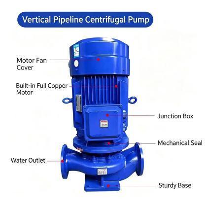
ISG Vertical Pipeline Centrifugal Pump electrical wiring requirementProper electrical wiring directly impacts the long-term operational safety, energy efficiency, and service life of inline vertical pipeline centrifugal pump systems. Even minor wiring errors can lead to unexpected tripping, abnormal motor heating, internal component damage, or unplanned downtime that disrupts entire fluid transfer loops. All wiring work must follow local electrical codes, site safety regulations, and manufacturer documentation to establish a stable, protected power connection that matches the pump’s actual operating conditions.
Pre-wiring site and equipment verificationBefore any cable connection begins, confirm that the on-site power supply voltage and frequency fully align with the parameters marked on the motor nameplate. Mismatched voltage levels will cause the motor to draw abnormal current during startup and continuous operation, accelerating insulation aging and increasing the risk of winding burnout. Check the integrity of all incoming power lines, control circuits, and protective devices to ensure there is no visible damage, exposed conductor, or loose connection point that could create hidden safety hazards. Verify that the ambient temperature and humidity at the installation location fall within the motor’s specified operating range, and confirm that the surrounding area is free of conductive dust, corrosive vapor, or standing water that could compromise electrical safety. Inspect the motor terminal box to make sure all internal connection points are secure, the insulation layers are intact, and no foreign debris from transportation or storage remains inside the enclosure. Wiring configuration and connection standardsSelect the correct wiring method based on the motor’s rated power and design specifications, following standard three-phase asynchronous motor connection conventions. For units designed for star connection, ensure all six winding terminals are properly grouped and connected to form a stable neutral point before linking to the three-phase power lines. For delta connection configurations, confirm that each phase winding is connected in the correct sequential order to avoid phase imbalance that would cause uneven torque output and excessive current fluctuation. For larger pump systems that require reduced starting torque, follow the star-delta wiring sequence strictly to ensure the transition between startup and full operation proceeds smoothly without sudden current surges that shock the entire circuit. All cable cross-sections must be sized to carry the maximum rated operating current and short-term startup current without excessive voltage drop along the line. Each terminal connection must be tightened to the torque value specified in the electrical documentation, with no bare copper exposed outside the terminal block and no stray strands of conductor that could cause short circuits. Grounding and protective circuit setupA reliable grounding system is one of the most critical safeguards for preventing electric shock and reducing electrical fault risk in vertical pipeline centrifugal pump installations. Connect the dedicated protective grounding terminal on the motor base directly to the site’s main grounding grid using a continuous, low-resistance conductor that meets local electrical code requirements. Never use the pipeline, pump body, or unrelated structural components as a substitute for a formal protective grounding path, as this can create dangerous floating voltage conditions during a fault event. Install appropriate overload protection, short-circuit protection, and phase loss protection devices in the control loop to automatically cut off power when abnormal current, missing phase, or locked rotor conditions occur. These protective settings must be calibrated to match the motor’s rated current, ensuring they activate before winding overheating or mechanical damage can take place. All control switches and isolation devices must be clearly labeled and positioned within easy reach of operators, so power can be disconnected immediately during maintenance or emergency situations. Post-wiring inspection and pre-operation testingAfter all wiring work is complete, perform a full visual check to confirm every connection point is secure, no wiring terminals are left loose, and no conductors are in contact with moving parts or high-temperature motor surfaces. Use a megohmmeter to measure the insulation resistance between each phase winding and the motor housing, making sure the measured value meets the minimum safety requirement specified for the equipment. Before the pump is fully connected to the piping system, carry out a short-duration point test to verify the motor rotation direction matches the directional arrow marked on the pump casing. If the rotation direction is incorrect, shut off power immediately and swap any two of the three phase lines to correct the sequence, as reverse operation will drastically reduce performance and cause unnecessary wear on impeller and seal components. Document all wiring parameters, protection settings, and phase sequence verification results in the site equipment log, so future maintenance personnel have clear reference information for subsequent inspections and troubleshooting. |